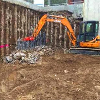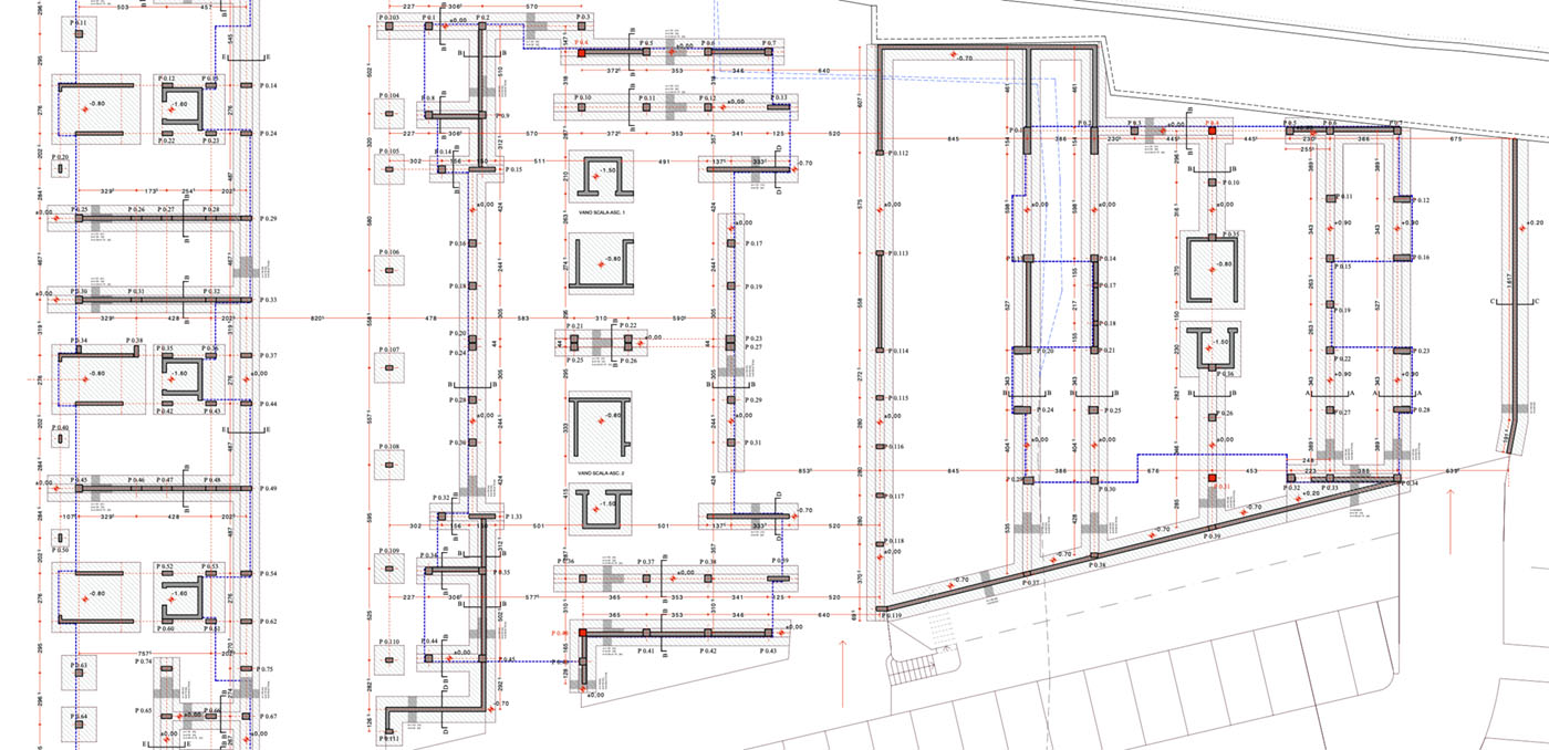
Designing a foundation system is also a team effort. The first necessary step is for engineers and geologists to define the soil investigation program, which very often also requires exploratory test pits, or a preliminary assessment of archaeological risks. Soil investigation is typically performed by driving a hammer-driven pile under controlled physical parameters, from which data on the soil’s resistance to the advance of the pile tip is obtained. It is therefore necessary to have a reliable map of underground utilities (sewer lines, water mains, public and private power lines, telephone and fiber-optic lines, natural gas lines, etc.) in order to be reasonably certain that no damage will be caused during drilling.
For larger-scale projects, geotechnical surveys are also conducted to extract soil cores down to the depths under investigation: the samples are examined for quality and then sent to a laboratory, and the data are compared with indirect data obtained from penetrometer tests.
Next, dynamic soil characterization tests are conducted using MASW (Multichannel Analysis of Surface Waves) tests, a non-invasive geophysical survey used to determine the velocity profile of vertical shear waves in the subsoil. This method allows for the calculation of soil stiffness, and the determination of the subsoil category for seismic design standards, generally to a depth of 30 meters. To determine the depth of the water table and its fluctuations, at least one piezometer is installed.
The entire set of tests must be capable of determining the mechanical properties of the soil as a function of depth, so that the geologist and engineer can jointly evaluate the most advantageous choice regarding the depth of the foundation bearing surface. Once a hypothesis on this point has been established, the structural model can evaluate one of the most delicate aspects of structural design: the interaction between the soil and the structure. Although complex numerical analyses must be performed, in summary we can say that it is first and foremost necessary to limit long-term settlement (especially for structures to be built adjacent to existing structures) and ensure that differential settlement is kept to a minimum, so as to prevent one part of the foundation from settling more than another, a situation that can alter the performance of the structural system and, in the most severe cases, trigger a series of damages to all associated structures (masonry, flooring, utility lines, etc.).
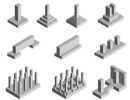
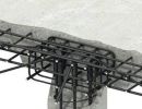
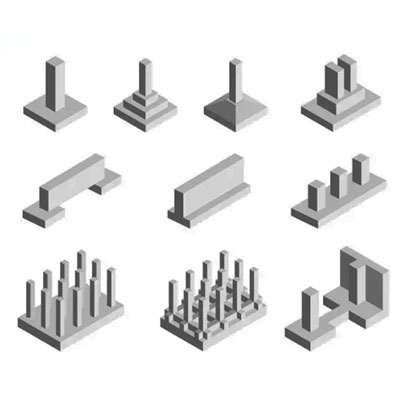
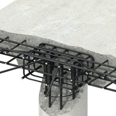
Once the layout plan has been defined, the reactions that the soil transmits to footings, inverted beams, foundation slabs, etc., are known, and thus the actual foundation elements can be designed, specifying the type of concrete to be used, the geometry of the reinforcement, the quantities of concrete, steel, and formwork—which, when imported into the BIM model, are incorporated into the analytical quantity takeoff for the works.
The beams, footings, and all foundation elements must then be drawn one by one, with all the details necessary for the construction of the structure. Below is an example of the approximately 70 construction drawings for the building whose general foundation plan we presented above.
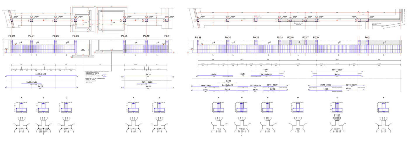
The production of the design drawings is carried out within the structural analysis software, which then performs the checks for each element (typically, for each beam, 25 cross-sections along its axis are checked, each for various load combinations and different limit states, depending on the type and significance of the structure). For durability verification purposes, rigorous checks are also performed on the foundations, to prevent microcracks that could reduce the protection of the reinforcing bars against corrosion.
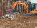
Verifications during the construction phase must ensure that the soil quality meets expectations: if necessary, the design engineer, in consultation with the geologist, will order local remediation of the subgrade through compaction using a heavy roller or the removal of loose material and local improvement.


Foundation and underpinning
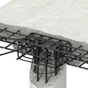
Reinforced concrete structures
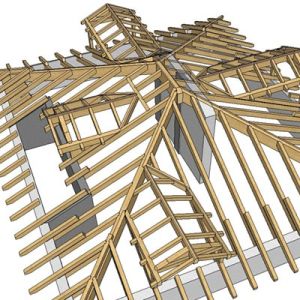
Timber structures
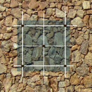
Masonry reinforcement
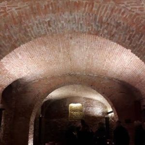
Vaults systems reinforcement
Timber subsystems reinforcement
Steel structures

Retaining walls