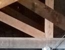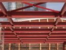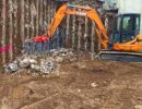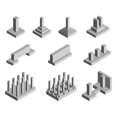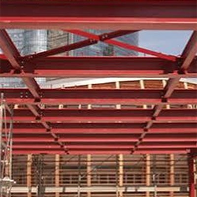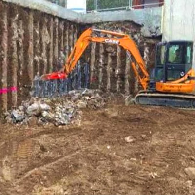
We rarely use concrete in renovation or restoration projects, so the issues discussed here, typically apply to new construction (as in the case shown here, following the demolition of a decommissioned industrial complex).
The starting point for the design is, of course, the architectural plan, and a significant portion of the structural design is derived directly from it. In fact, the sizing of a concrete beam or column is an indeterminate analytical problem, with more variables than equations: in other words, an infinite number of beams can be designed to fulfill the same function. Therefore, before moving on to the actual calculation model, it is crucial to correctly pre-dimension all the main elements - beams, columns, and structural openings for ventilation, utilities, or elevators - in order to verify the first level of interdisciplinary compatibility against the architectural design.
We do this using a proprietary calculation tool, developed specifically to provide reliable data - directly within Archicad - on the dimensions of structural cross-sections and the quantities of reinforcing steel required. After this step, we harness the true potential of BIM: the structural model is transferred from Archicad to the selected calculation software (we have two or three alternatives depending on the needs), ensuring a perfect geometric match with the architectural model.
Once the model has been refined (internal constraints, loads and load combinations, materials, etc.), the actual numerical simulation is performed, typically using the modal analysis method. The analysis of deformations (both static and dynamic) may suggest certain adjustments, which are first verified for their structural effectiveness; then, still within the BIM interface, their compatibility with the architectural design is checked, and the necessary geometric modifications are made to the architectural design.
Based on our experience, this process requires no more than one or two passes; thereafter, the final calculation model can proceed to generate the calculation reports, the final drawings for the structural members, the construction details, and everything needed for the quantity takeoff, since a BIM interface is used between the material quantities entered into the model and the software for the analytical cost estimation of the works.
Further minor refinements may involve checking for conflicts with minor utility routes: these are managed using specialized software capable of comparing the MEP BIM model with the structural BIM model, and their significance is assessed, allowing decisions to be made (prior to construction) regarding the addition of any further openings in the structures or partial modifications to the planned utility routes. The goal is to identify as many of these critical issues as possible during the design phase, so that construction can proceed as smoothly as possible.
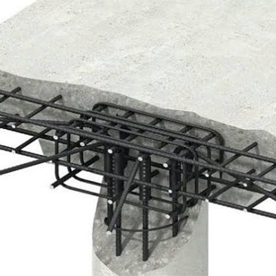
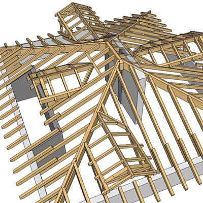
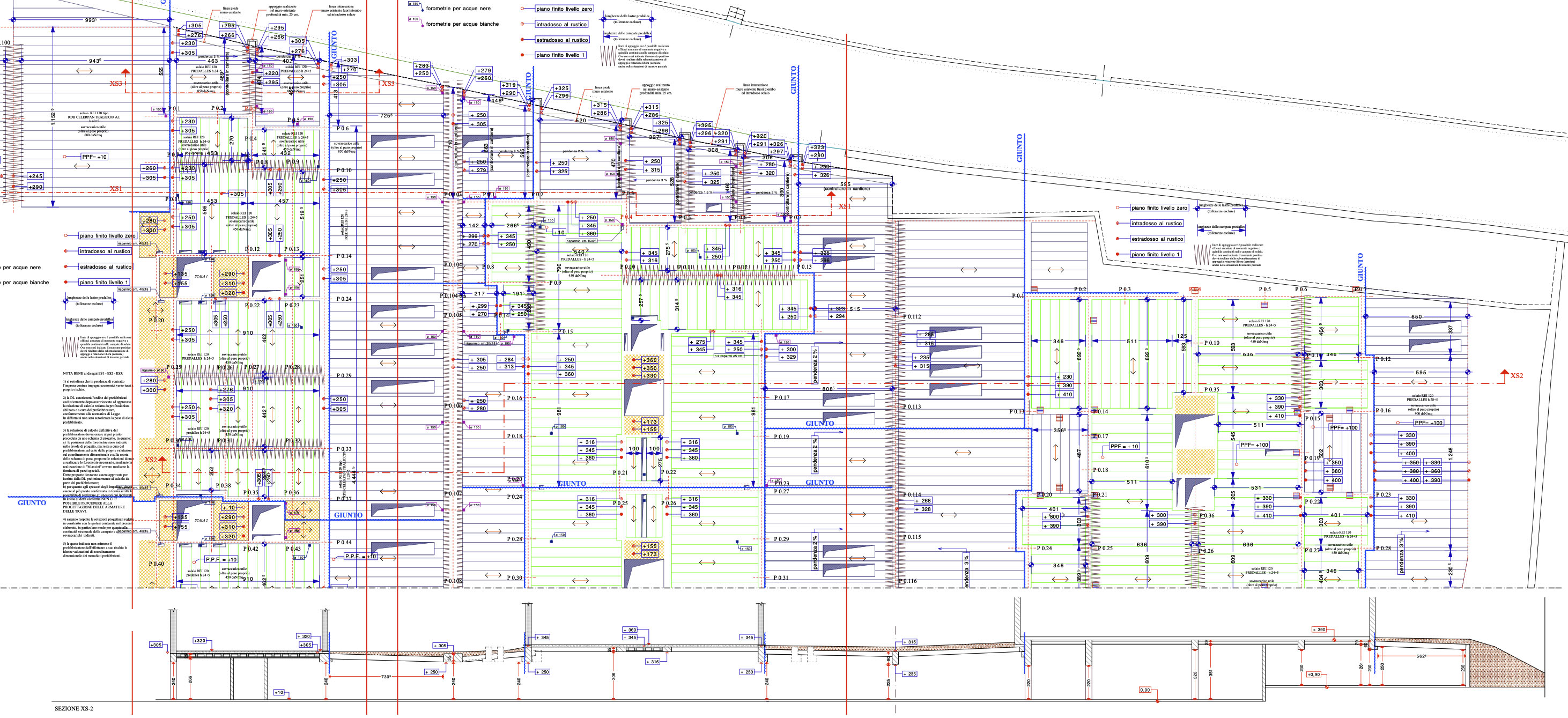
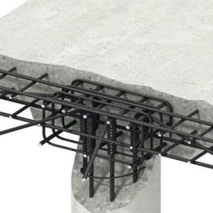
The project described above - of which we are presenting a partial view of the deck - required the production of over 200 construction drawings, to build a total building volume of approximately 80,000 cubic meters. Thanks to this level of engineering, the foundations were laid out in January, and by August, the wooden roofs were being installed. The entire process It took only 8 months.
In various contexts, we have used, as appropriate, cast-in-place concrete, prestressed concrete, precast slabs, hollow-core concrete, REP beams, composite steel-concrete structures, ribbed or lightweight slabs... These decisions always depend on optimizing design requirements, while also taking into consideration the site’s needs regarding logistics, material handling, procurement, assembly sequences, and construction timelines.
The structural design is therefore always discussed in terms of ergonomic and safety issues on the construction site, resulting, once again, in a highly interdisciplinary process.


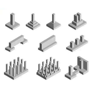
Foundation and underpinning
Reinforced concrete structures
Timber structures
Masonry reinforcement
Vaults systems reinforcement
Timber subsystems reinforcement
Steel structures

Retaining walls